Technologies
SLCE watermakers, with reverse-osmosis phenomenon and its exclusive technologies, works at improving the user experience.
You will find below, among others, the explanation of reverse-osmosis principle, the description of energy recovery devices...
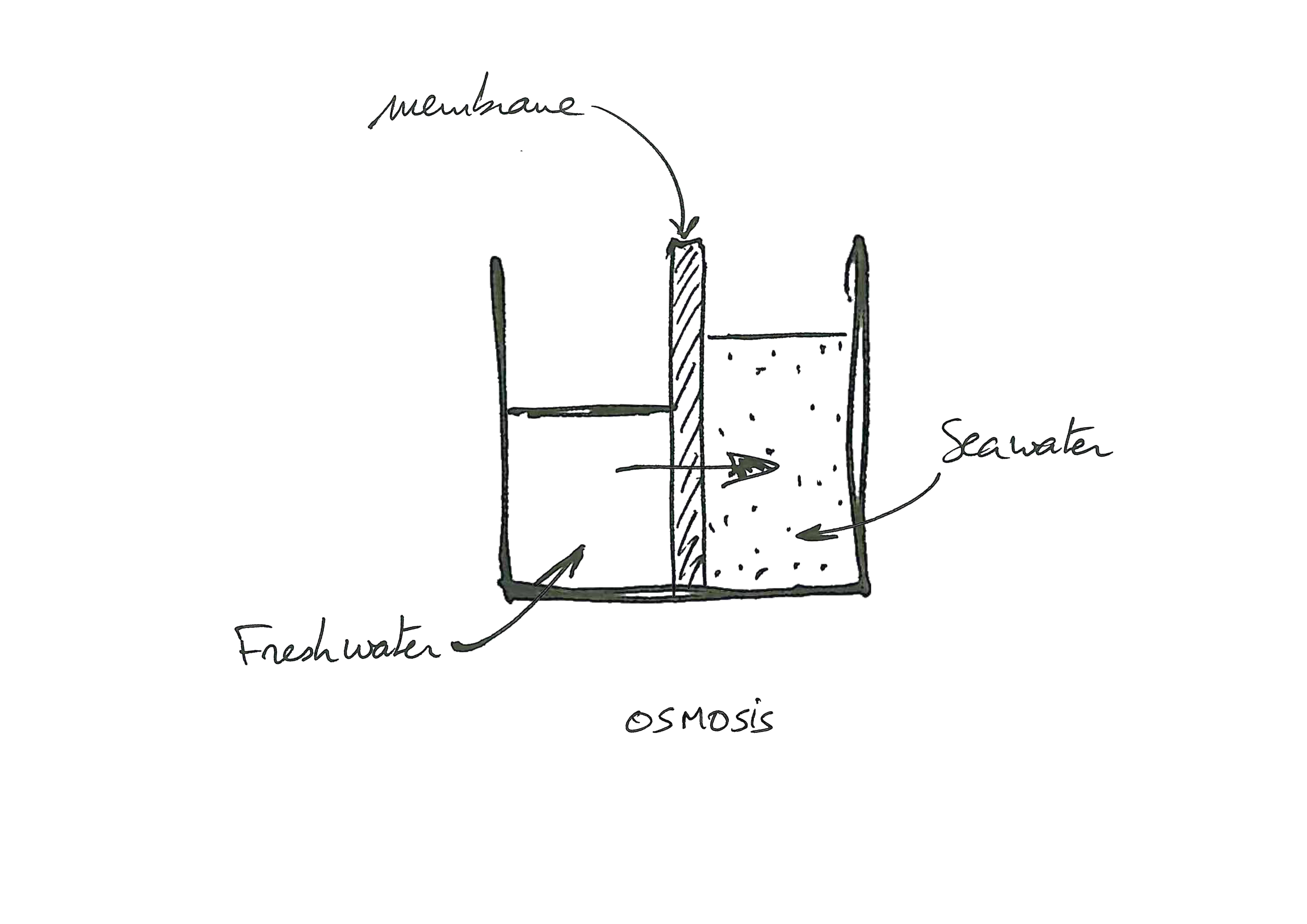
~ Reverse osmosis principle ~
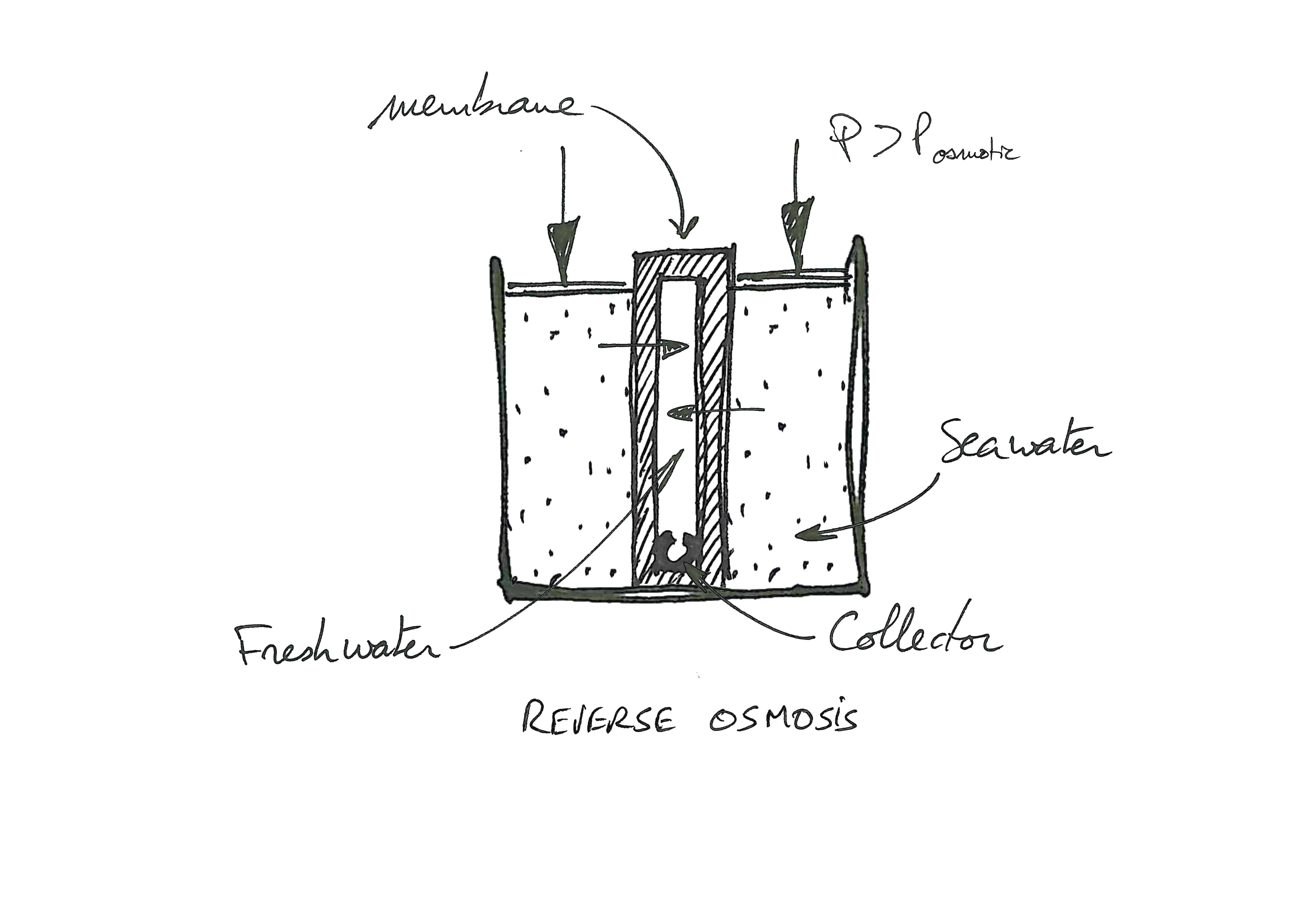
A container is divided in two sealed parts by a semi-permeable membrane.
The right side is filled up with seawater,
The left side is filled up with freshwater,
With no external intervention, a freshwater flow passes through the membrane from the freshwater compartment to the seawater compartment.
This is the phenomenon of OSMOSIS.
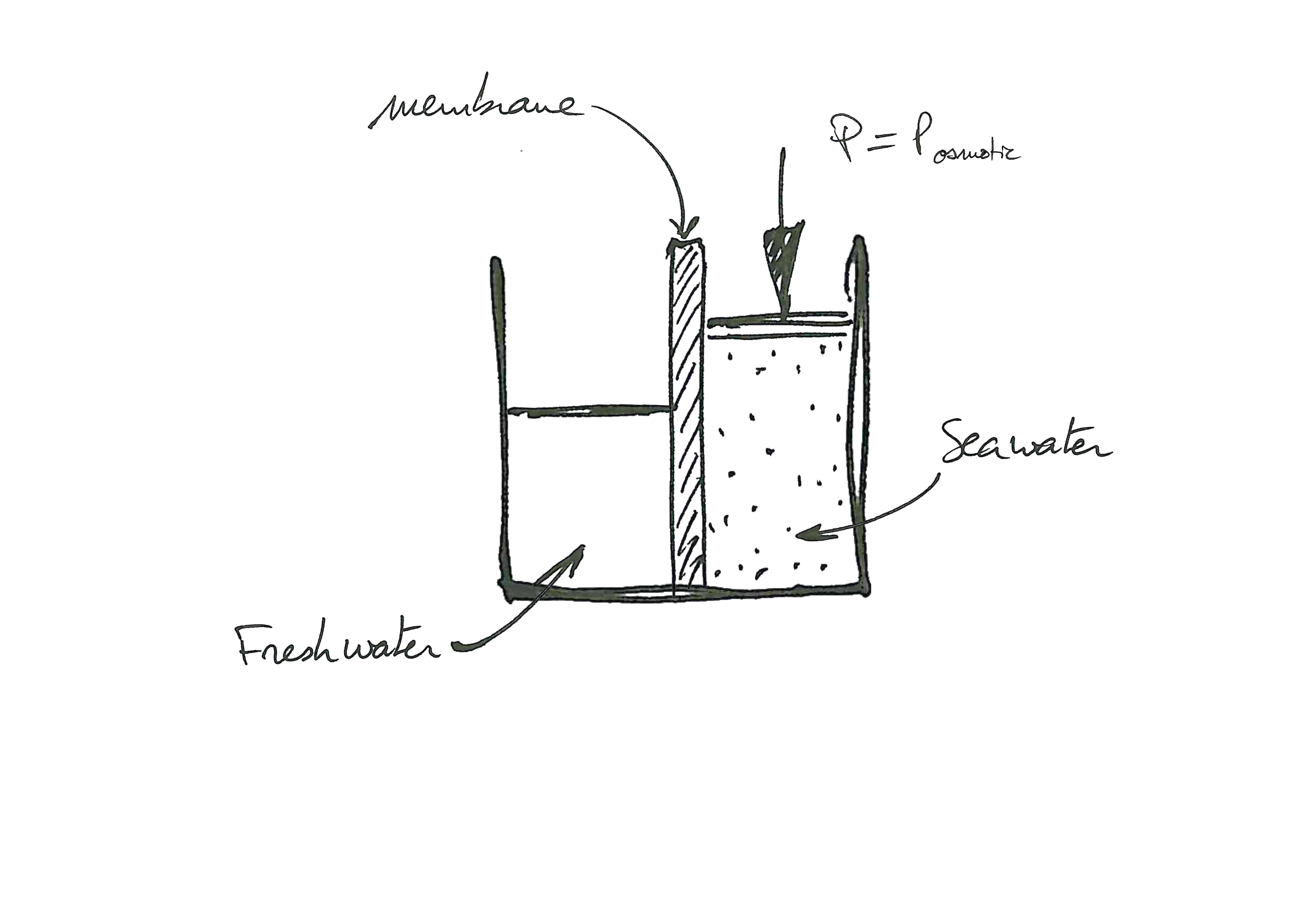
A pressure is now applied on the seawater compartment..
The pressure sufficient to stop the osmosis phenomenon is called osmotic pressure.
In the case of seawater, the osmotic pressure is approximately 28 bar.
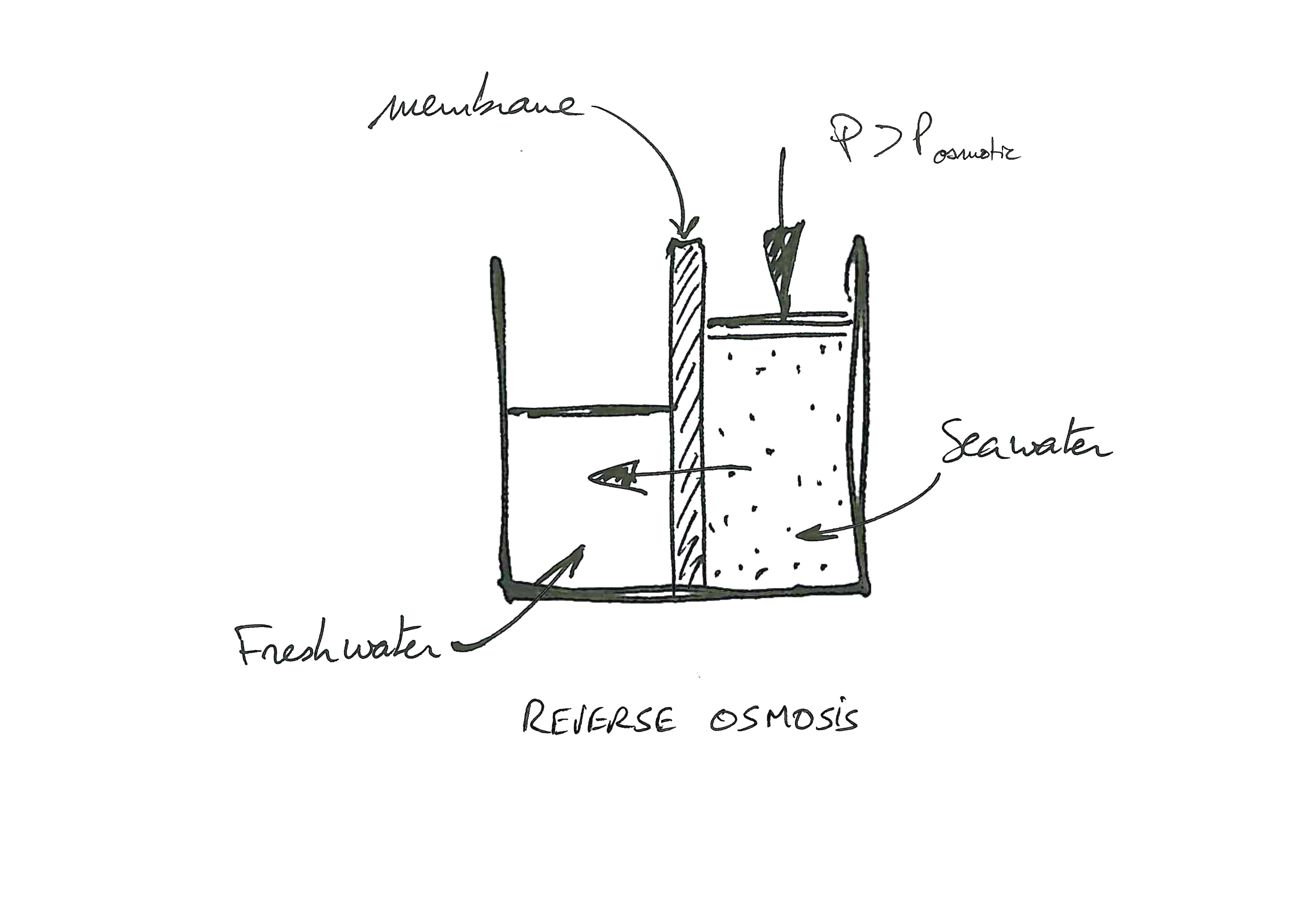
If a pressure higher than the osmotic pressure is now applied, the flow of fresh water passing through the membrane is reversed.
The salts present in the sea water are stopped by the semi-permeable membrane. Thus, only fresh water flows through the membrane from the seawater compartment to the fresh water compartment.
This is the phenomenon of REVERSE OSMOSIS.
A semi-permeable membrane is different from a filter.
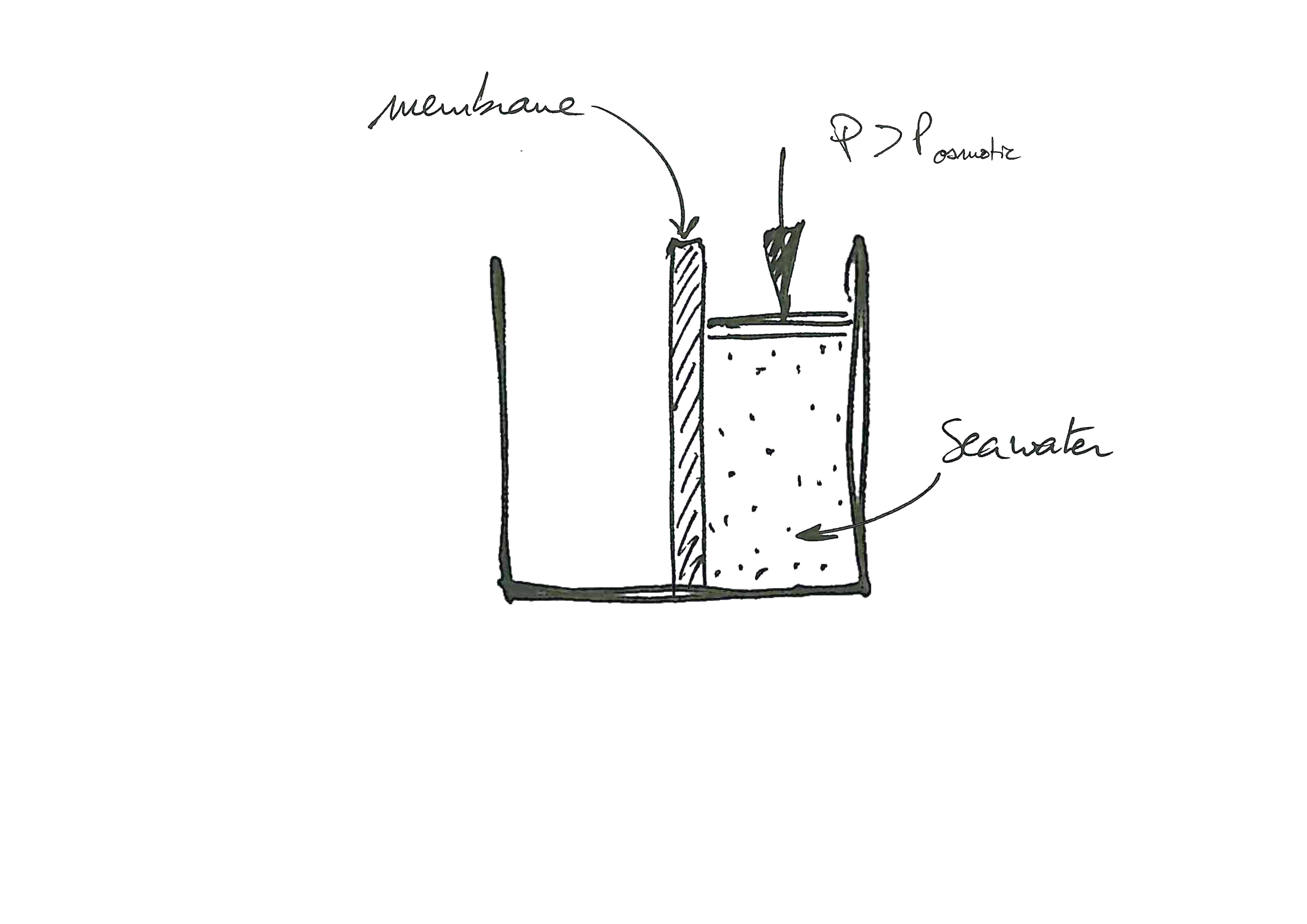
Initially, the freshwater compartment is empty and only the seawater compartment is filled up. Despite the high pressure applied in the seawater compartment, no flow will pass through the membrane.
To put it in a nutshell, to obtain the phenomenon of osmosis, one must have:
- A semi-permeable membrane
- A couple sea water / fresh water
To obtain the phenomenon of reverse osmosis, it is necessary, in addition, to have:
- A pressure higher than the osmotic pressure applied on the seawater compartment.
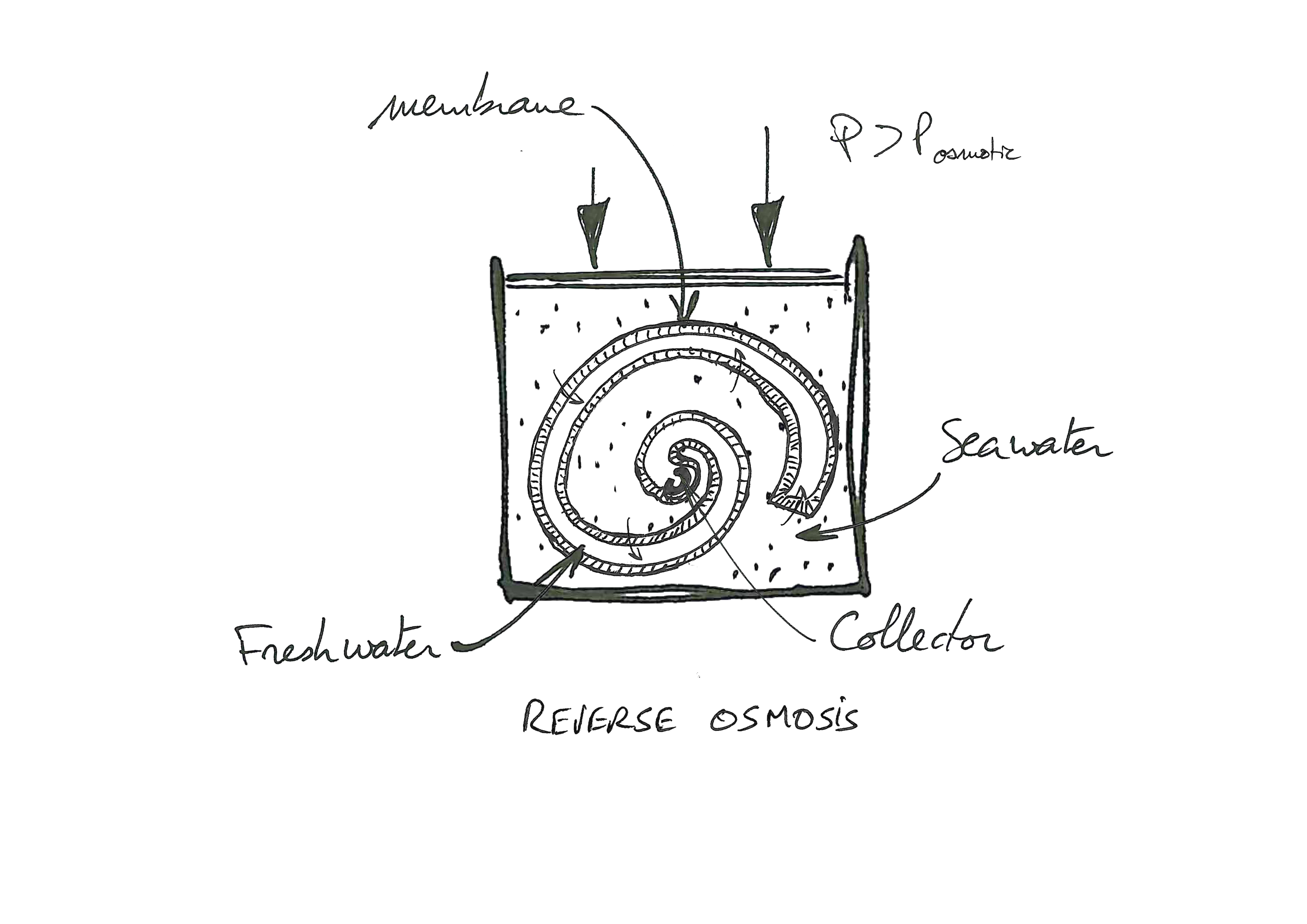
~ Membrane construction ~
In this configuration, to produce 215 L/h of freshwater, around 7m² of membrane are required. The footprint of such an installation would lead to a number of issues.
In order to reduce the size of the installation, the membrane is folded and glued to the edges so as to form a pocket in which fresh water is collected. Thanks to this configuration, the size of the installation drops to 3.5m². Although more compact, this configuration can be further improved.
To further improve the compactness of the membrane, it is wrapped around the freshwater collector, forming a spiral.
For a production of 215 L/h, the membrane has now a diameter of 100mm and a length of 1m.
~ Prefiltration ~
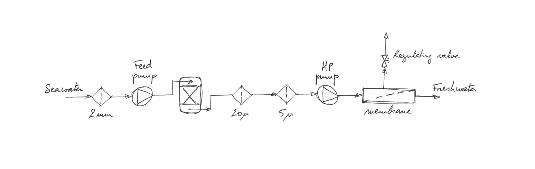
The efficiency of the pre-treatment of the seawater is critical to keep the performances of the plant stable in the long run.
This step, when properly designed, remove most of the impurities (particles and colloïds). Thus, it protects the high pressure (HP) pump and the membranes from a premature fouling.
The water pumped by means of the booster pump passes through a sand filter (SF) which performs mechanical filtering. This filter retains the biggest particles suspended in the seawater in order to increase the life span of the following filtration cartridges.
The water then passes through two successive filters with, respectively, 20μ and 5μ cartridges. They complete the clarification of the water before it passes through the HP pump.
The entire pre-treatment process is designed to facilitate maintenance and extend the life of the membranes and the HP pump.
~ Cleaning in place (C.I.P.) ~
The flushing of the membranes with osmosed water, although essential to prolong the lifespan of the material, is not sufficient to remove all the impurities and minerals clogging the membranes.
It is therefore necessary to carry out a chemical cleaning according to the recommendations contained in the technical manual provided with each machine.
It usually consists in three cycles: alkaline, acid, alkaline; each followed by a flushing cycle with fresh water.
~ Energie recovery devices (E.R.D.) ~
In a conventional system, the entire seawater pumped is pressurized. Much of the energy spent for this purpose is dissipated in the discharge.
In an effort to save energy, our recovery devices are a unique asset. They reduce the consumption of the osmosis by transferring the energy available in the reject to the seawater.
We use two proven and recognized recovery devices: one linear and one rotary.
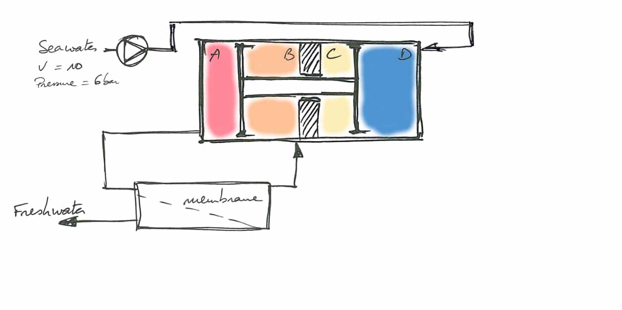
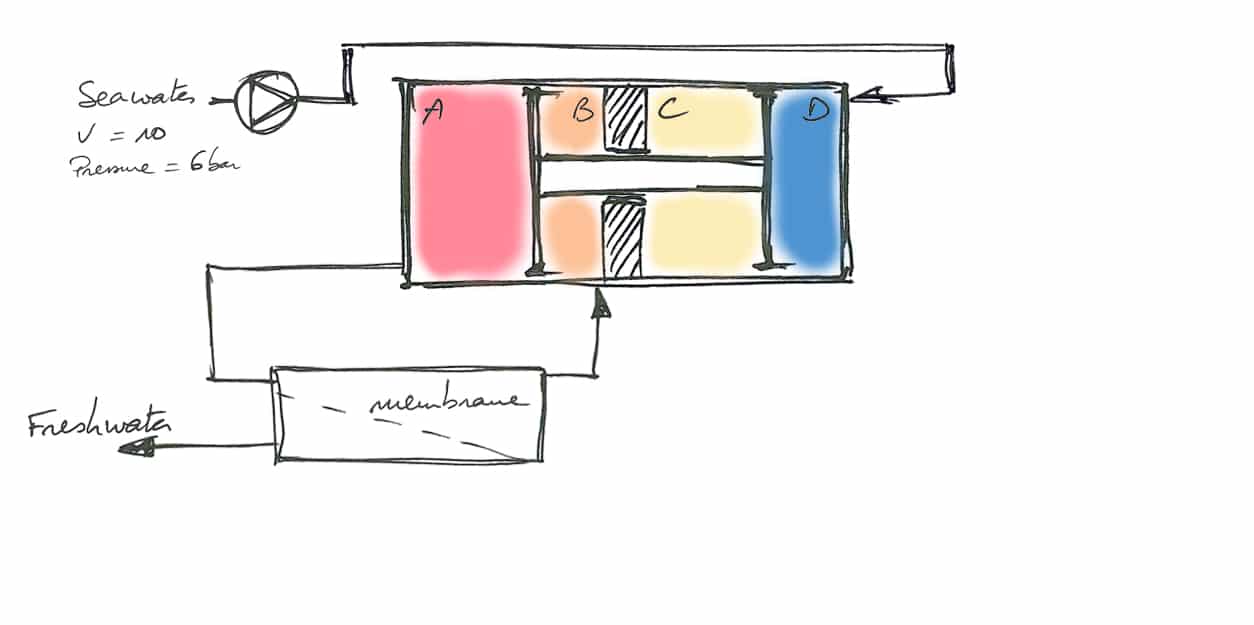
Linear E.R.D.
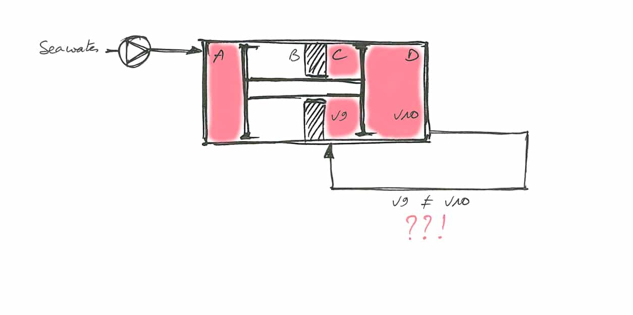
A double sealed piston separates a cylinder into four distinct compartments: A, B, C, and D.
At the beginning of the cycle, chamber D has a volume of 10 and chamber C a volume of 0.
At the end of the cycle, chamber D will have a volume of 0 and chamber C a volume of 9. The missing volume of the chamber C corresponds to the volume occupied by the piston rod.
The chambers C and D are connected and filled (step only necessary for the presentation of the principle of the linear ERD).
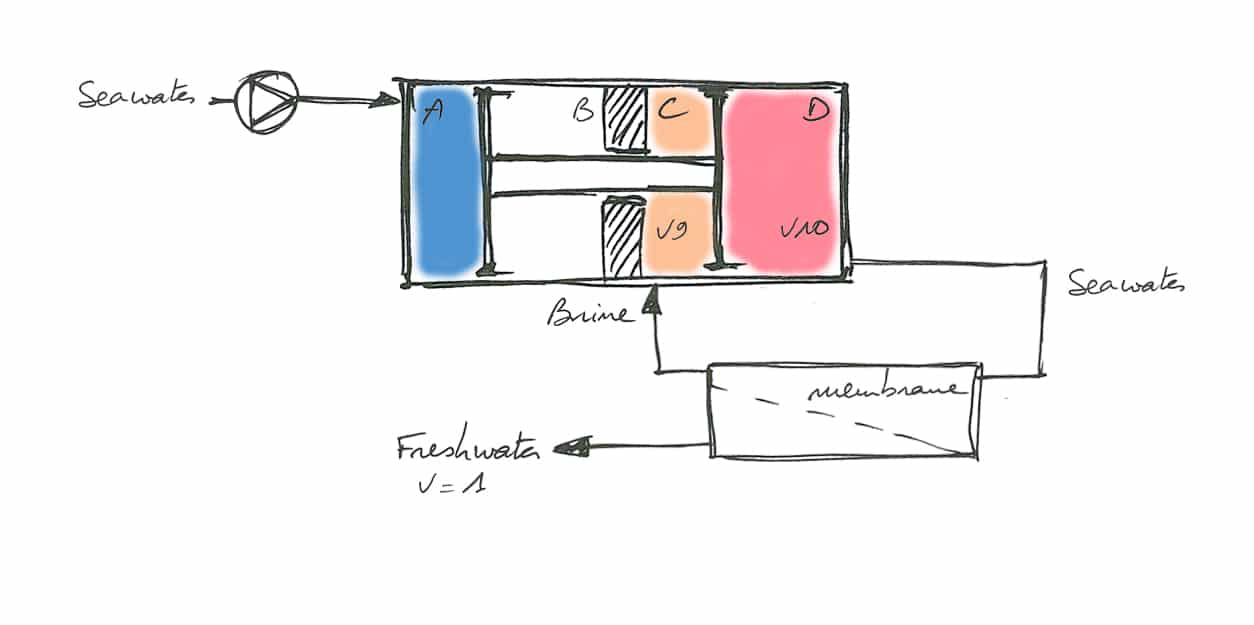
A pump feeds chamber A.
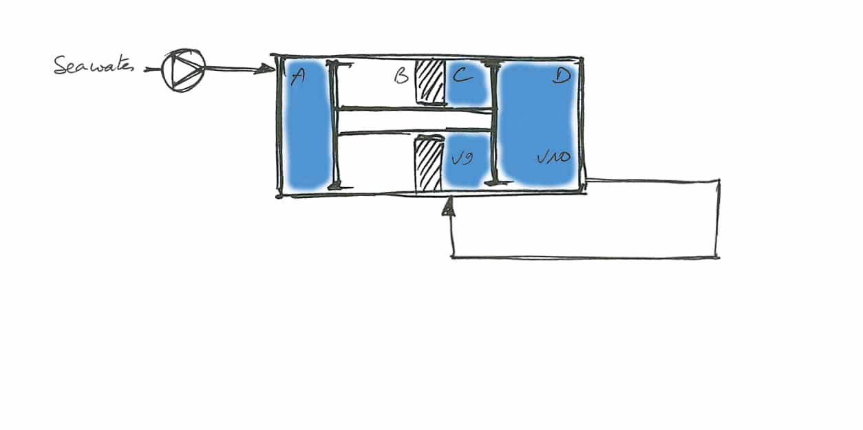
Because of the difference in volume between chamber D and C and the incompressibility of water, the piston is blocked.
Discharging the excess volume would allow the piston to move.
This excess volume is converted into fresh water through a reverse osmosis membrane installed between chambers C and D.
The 10 volumes of water from chamber D are admitted into the membrane.
The membrane thus produces 1 volume of fresh water, the remaining 9 volumes are transferred into chamber C.
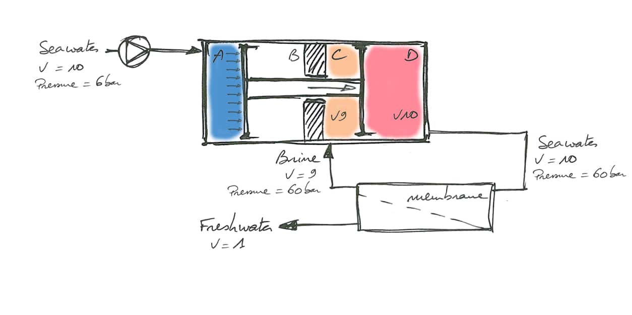
The booster pump provides pressure to the linear ERD. This pressure is progressively multiplied up to 60 bar by a section ratio in order to supply the membrane.
The discharge of 9 volumes under pressure from the membranes are sent into chamber C. It thus contributes to the drive of the piston.
These 60 bar are obtained as follow:
- The pump supplies chamber A at a pressure of 6 bar. This pressure is applied on a surface of 10. That is an overall effort of 10×6 = 60. (Force = Section x Pressure)
- After several cycles, the reject of the membrane feeds chamber C at a pressure of 60bar on an a section of 9. That is to say an overall force of 9 × 60 = 540
- The combined forces coming from chamber A and chamber C, ie 540 + 60 = 600, is transferred to chamber D. The latter having a surface area of 10, this represents 10 volumes at 60 bar (10 × 60 = 600)
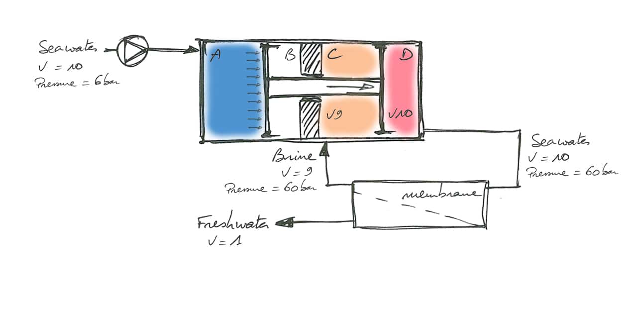
Once the piston has reached the end of its stroke, a distribution system makes it possible to reverse the stroke. Now :
- The sea water feeds chamber D
- The membrane is connected between chambers A and B
- Brine in chamber C is discarded
Units equipped with this type of linear E.R.D. consume less than 150W for a production of 35L/h, compared with 375W for a conventional system.
This linear E.R.D. developed by SLCE watermakers is certified by Bureau Veritas.
In addition to its excellent energy performance, it is characterized by its acoustic and vibratory discretion.